2024-09-18 Ask OpenAI-o1: motor svpwm calculation
- Sure, I can help with that! Space Vector Pulse Width Modulation (SVPWM) is a technique used to control three-phase inverters in motor drives. It aims to generate a three-phase output voltage with the desired amplitude and frequency while minimizing harmonics and maximizing efficiency.
Detail
- Here's a basic overview of the calculation process for SVPWM:
- 1. Understand the Coordinate System:
- α-β Coordinate System: This is a stationary reference frame where the three-phase voltages are transformed into two orthogonal components.
- d-q Coordinate System: This is a rotating reference frame where the voltages are transformed into direct (d) and quadrature (q) components.
- 2. Transform the Input Voltages:
- The three-phase voltages 𝑉𝑎, 𝑉𝑏, and 𝑉𝑐 are transformed into α-β coordinates using Clarke’s transformation:
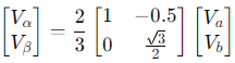
Where 𝑉𝑐 can be derived as 𝑉𝑐 = −𝑉𝑎−𝑉𝑏.
- 3. Transform to d-q Coordinates:
- Use Park’s transformation to convert the α-β coordinates to d-q coordinates:
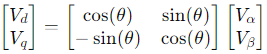
Where


𝜃 is the angle of the rotating reference frame.
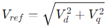
- 4. Calculate the Reference Voltage Vector:
- The reference voltage vector 𝑉𝑟𝑒𝑓 is determined in the d-q frame:
- And the angle of the reference vector is:

- 5. Determine the Sector:
- The reference vector is located in one of the six sectors of the hexagon in the α-β plane. Determine which sector 𝑉𝑟𝑒𝑓 falls into.
- 6. Calculate the Duty Cycles:
- Based on the sector, calculate the duty cycles for the adjacent active vectors and the zero vectors. The duty cycle for each vector is found by solving a set of linear equations.
- 7. Generate the PWM Signals:
- Use the calculated duty cycles to generate the PWM signals for the three-phase inverter switches. This typically involves using a lookup table or interpolation to determine the exact timing of the switching pulses.
- Example Calculation Steps:
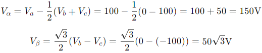
- 1, Transform Phase Voltages to α-β: Given 𝑉𝑎=100V, 𝑉𝑏=0V, and 𝑉𝑐=−100V,
- 2, Transform α-β to d-q: Assume 𝜃=30∘ (or 𝜋/6 radians),
𝑉𝑑=𝑉𝛼⋅cos(𝜃)+𝑉𝛽⋅sin(𝜃)
𝑉𝑞=−𝑉𝛼⋅sin(𝜃)+𝑉𝛽⋅cos(𝜃) - 3, Determine Sector and Duty Cycles: Depending on the value of 𝑉𝑑 and 𝑉𝑞, identify the sector and calculate the duty cycles for the active vectors and zero vectors.
- 4, Generate PWM Signals: Use the duty cycles to create PWM waveforms that drive the inverter.
- This process involves several detailed calculations, and the actual implementation can vary depending on the specifics of your motor drive system and control strategy. If you have specific values or need more detailed guidance, let me know!


TAGS
- 31 person(s) visited this page until now.